Headlines
In this article, you’ll find out everything about our new module – the Send & Show module, a module for controlling LED lights and strips.
What is the Send&Show module?
The new module seamlessly connects the physical and virtual worlds once again. It is ideal for trade fairs, showrooms or events. When you click on a link in presono, not only is content displayed, but signals are also sent to the LED strips at the same time.
Here is an example:
So, if you have a display featuring several product models or similar items in front of you, along with a (touch) screen running presono, you can select a product group in presono, for example. This takes you to a detail page for the product group in presono, and at the same time, the models belonging to that product group are illuminated by the LED strips. If you then click on a product, that product is illuminated again (e.g. brighter or in a specific colour) and the product’s detail page is displayed in presono.
For the LED strips, different brightness levels, colours and animations (flashing, brightening, etc.) can be set.
The module can, of course, be combined with all other presono modules, such as the Remote Control module, which allows specific content to be triggered or displayed not only on the operator screen (touchscreen) but also on other screens (e.g. behind the models). But also, for example, with our Scan&Show module, where scanning NFC tags or barcodes brings up content directly in presono – at the same time, a product can also be illuminated with LEDs, for instance.
The module is, of course, also capable of operating offline.
Example image
How does it work?
The entire setup must be done once in advance in order to configure everything. The content can, of course, be prepared in advance in presono, but some settings must be configured using the actual devices, as these settings are saved on the devices themselves.
What do I need?
- A PC (e.g. a mini PC) on which the presono app can be installed, with a direct USB port on the device
- a user account (ideally a presenter account with read access to the exhibition content)
- an Arduino LED controller (provided by presono)
- LED strips
Below you will find a detailed description of how to configure the technical components.
You can find out how to assign the LED commands to a button in your slide after the technical description here: Linking
Configuring the controller
To configure the controller, the trade show device must be used, and the configuration or ‘detection’ of the controller can then be carried out directly within the presono interface under Settings. You therefore connect the Arduino controller to the mini PC and configure the device in this way.
IMPORTANT: Place the links on the objects that will be displayed on the device to which the controller will later be connected. For example: if you have a setup with a touchscreen at the front, an LED wall at the back and models in front of you, you can either place the links on the slides that will be displayed on the LED wall and connect the controller to the PC behind the LED wall. Option 2 would be to connect the links and the controller to the ‘remote control’ – i.e. at the front by the touch screen – and link them there. If a link is called up on a device to which no controller is connected, no LED commands will be executed.
If the controller is later reconnected to the same device, presono automatically recognises the Arduino and you can start using it straight away. The only important thing here is that this setting is saved on the device, i.e. in the app. If a different device is used, reconfiguration is required.
- Disconnect the LED strips from any power supply (if they are still connected)
- Connect the LED strip to the controller as shown. The controller supports up to 12 LED strips; the connections are arranged as shown, alternating from left to right between a connection for the LED strip’s data line and a connection for the LED strip’s ground (GND). The V+ line of the LED strip is not connected to the Arduino and should be secured so that no exposed wire can come into contact with the controller.
- Please make a note of which data pin each LED strip is connected to – this corresponds to the LED port during configuration (see below).
- Connect the power supply to the LED strip.
- Connect the LED controller to the mini PC using the USB cable provided.
- Please note that it may take a few seconds for the presono app to recognise the LED controller if the connection is established whilst the app is open.
Add device
To add a device, go to the settings under ‘Serial devices’.
Then click on ‘Add device’; if the device is already plugged in, you can click directly on ‘Select from connected devices’, and the details at the top will be filled in automatically.
Below that, you will find the device ID, the baud rate and the commands specifying what should happen when the device is connected initially. The ‘Set Up’ command requires all connected LED strips to be initialised once (i.e. you must specify what should happen on start-up). You can find details of what needs to be entered in the next section:
At the end, click ‘Save’ to configure the controller for your device. Please note that this is saved on the device. So if you want to use a different device, you will need to add the device again.
LED configuration
presono provides a presentation or configurator directly within the presono interface for configuring the LEDs. This allows you to test the various configurations (directly connected LEDs can be controlled to test colours or brightness levels, for example) and the configurator then generates the values to be entered, which simply need to be assigned to the corresponding ‘button’ in the presentation.
Please note that you must start the presentation in the desktop app to be able to test the values directly. However, this does not have to be the final device to be used at the trade fair. The setup is then carried out on the final device as described below.
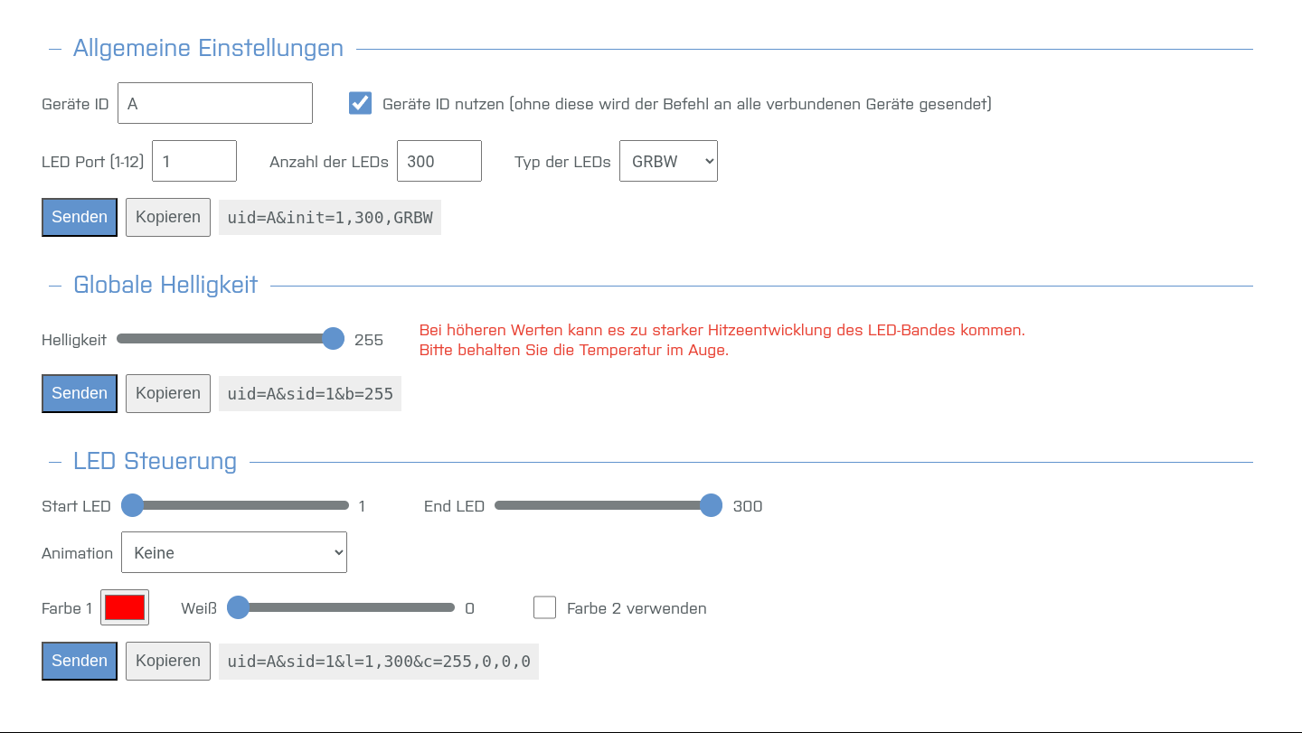
There are three types of commands that can/must be sent to the LED controller. These are divided into three different sections within the interface.
General settings
Each connected LED strip must be initialised once before it can be controlled; during this process, the number of LEDs and the type of LED control must be specified.
These initialisation commands (for starting up or connecting the LEDs for the first time) are saved on the device settings (see above) and do not need to be triggered by a slide or a link.
Device ID
The device ID is used to address a specific LED controller; this is particularly important when more than one controller is connected. The ID can be freely selected in the device settings. For example, ‘A’.
LED port
The LED port determines which LED strip is to be controlled; for the number, see the connection diagram above.
Number of LEDs
The number of LEDs connected to the LED port.
Type of LEDs
This determines the order in which the data from the various colour channels is sent. Please refer to the LED strip’s datasheet for details. For SK6812, the order is GRBW; for WS2815, it is GRB.
Global brightness
Here you can set the overall brightness of the entire LED strip.
In our tests, the SK6812 strips reached 85°C within a minute when set to full brightness with maximum colour values, and the temperature continued to rise; therefore, please keep an eye on the temperature of the LED strips. If they overheat, disconnect them from the power supply.
LED control system
With these settings, you can control specific sections of the LED strip and set colours or animations.
Up to 20 different sections with different colours or animations can be defined simultaneously per LED port.
If a section is defined that overlaps another, the overlapped section is deactivated. (e.g. if you define LEDs 1–20 as red and then 10–30 as green, LEDs 1–9 are switched off and 10–30 are green)
Start LED & End LED
These settings define the LED section for which a colour or animation is to be set. (e.g. 0–20)
Animation
You can define an animation for this area here; depending on the animation selected, there are additional parameters that can be set.
- None: Static colour; a second colour can be defined, in which case the LEDs will alternate between the two colours, but there is no animation.
- Flashing: The LEDs switch back and forth between two colours without a transition.
- Single colour change: The colour of the LEDs transitions smoothly from the first to the second colour and then remains at the second colour.
-
Continuous colour change: The LEDs switch smoothly back and forth between two colours.
Color
Here you can set the colour tones and, for LEDs with a separate white channel, the white level as well.
Linking
If you now want to trigger an LED command in your slide, so to speak, you need to link it. You have the following options:
- Perform actions when the slide opens
- Perform actions when leaving the slide
- Perform actions when clicking on a link
You can find out what the link should look like in the section above under ‘LED control’.
IMPORTANT: Place the links on the objects that will be displayed on the device to which the controller will later be connected. For example: if you have a setup with a touchscreen at the front, an LED wall at the back and models in front of you, you can either place the links on the slides that will be displayed on the LED wall and connect the controller to the PC behind the LED wall. Option 2 would be to connect the links and the controller to the ‘remote control’ – i.e. at the front by the touch screen – and link them there. If a link is called up on a device to which no controller is connected, no LED commands will be executed.
Please note that we recommend using only one type of link per slide – i.e. either an input or output action, or a link.
As a general rule: all commands are executed until they are overwritten by a new command. For example: if the first command makes the entire LED strip light up in blue, but the next command then makes only the second half light up in green, the first half of the strip will be turned off.
1. Perform actions when the slide opens & 2. Perform actions when the slide closes
You can find these settings at the top left of your slide under ‘Slide Automation’:
These settings apply to the entire slide, across all languages and in all presentations where this slide is used.
Click on one of the two options and then on ‘Serial port’. You can then enter your links under ‘Data’.
Multiple links should always be entered on separate lines:
In this case, LEDs 0 to 125 will be coloured purple and LEDs 125 to 300 will be coloured green/yellow.
It is not essential to specify the device ID here, unless multiple controllers are connected. If no ID is specified, the commands will be sent to all connected devices:
You can also remove the link:
Please note that we recommend using only one type of link per slide – i.e. either an input or output action, or a link.
As a general rule: all commands are executed until they are overwritten by a new command. For example: if the first command makes the entire LED strip light up in blue, but the next command then makes only the second half light up in green, the first half of the strip will be turned off.
3. Perform actions when a link is clicked
You can also apply an ‘LED command’ to a single element (e.g. a button) on your slide. You can either assign just the LED command, or a ‘normal’ link (e.g. to a slide, an overlay, etc.) and then the LED link as well.
The following elements can be used as links or buttons here:
- Images,
- entire sections of text,
- parts of text or
- gallery elements.
For example, if you want a product in your layout to simply light up when you click a button, click on ‘Link’ and then on ‘Serial port’.
Here you can enter one or more commands again.
However, if, for example, you want a product to be highlighted in your set up and an overlay to open at the same time, you first link your overlay as usual:
And then, under ‘Extras’, you can add a serial link (LED command):
Clicking the button will then activate both links.
Good to know
There are no limits to your creativity with this module either. Your setup can vary greatly – for example, a model display with a video wall and remote control, or simply a touchscreen featuring models that are highlighted. Similarly, with a machine or a model of a machine, a specific area or component can light up when you ‘log it in’ on a touchscreen. But these are just examples.
If you have any questions or ideas, please feel free to contact your contact person at presono directly or email info@presono.com. We’ll be happy to advise you and, of course, support you with the implementation.
Here is a summary of the key technical aspects:
What does presono provide?
If you wish to use our Send&Show module, we will send you the LED controller and also activate the feature for you within presono. The configuration presentation will also be activated for you. You can then get started straight away, create your content and assign it to the LED commands. To obtain the values, use the configuration presentation (note: in the desktop app, but this does not necessarily have to be the final device).
Set Up
Please note that a media player must be provided for each ‘output’ screen, and the Remote Control Module is required to control devices remotely.
So, for example, if you have a touchscreen terminal where you select products (which then highlight the models), and then two further screens where videos or other related content are shown when the products are selected, you will need:
- A mini PC + touch screen or a tablet for the remote control (must be a PC if the controller unit is connected here)
- A mini PC + (touch) screen or a tablet for the first video screen (must be a PC if the controller unit is connected here)
- A mini PC + (touch) screen or a tablet for the second video screen (must be a PC if the controller unit is connected here)
- The LED controller module (connected to one of the three mini PCs, where the links are also routed; supplied by presono)
- LED strips (connected to the controller)
- Our remote control module (remote control of other devices is not a core feature of presono) incl. equipment (router, hub, etc.)
For an installation without the remote control module, a touchscreen featuring the models would be ideal, for example. Alternatively, a touchscreen could be placed next to a machine or a model of a machine. When the presentation or slides are operated on the touchscreen, the models or machine parts are illuminated accordingly.
Set Up & Links
IMPORTANT: Place the links on the objects that will be displayed on the device to which the controller will later be connected. For example: if you have a setup with a touchscreen at the front, an LED wall at the back and models in front of you, you can either place the links on the slides that will be displayed on the LED wall and connect the controller to the PC behind the LED wall. Option 2 would be to connect the links and the controller to the ‘remote control’ – i.e. at the front by the touch screen – and link them there. If a link is called up on a device to which no controller is connected, no LED commands will be executed.
Linking
Please note that we recommend using only one type of link per slide – i.e. either an input or output action, or a link.
As a general rule: all commands are executed until they are overwritten by a new command. For example: if the first command makes the entire LED strip light up in blue, but the next command then makes only the second half light up in green, the first half of the strip will be turned off.
You might also be interested in: